 Specialty Casters
 Gate Casters
 BBQ Pit & Smoker Casters
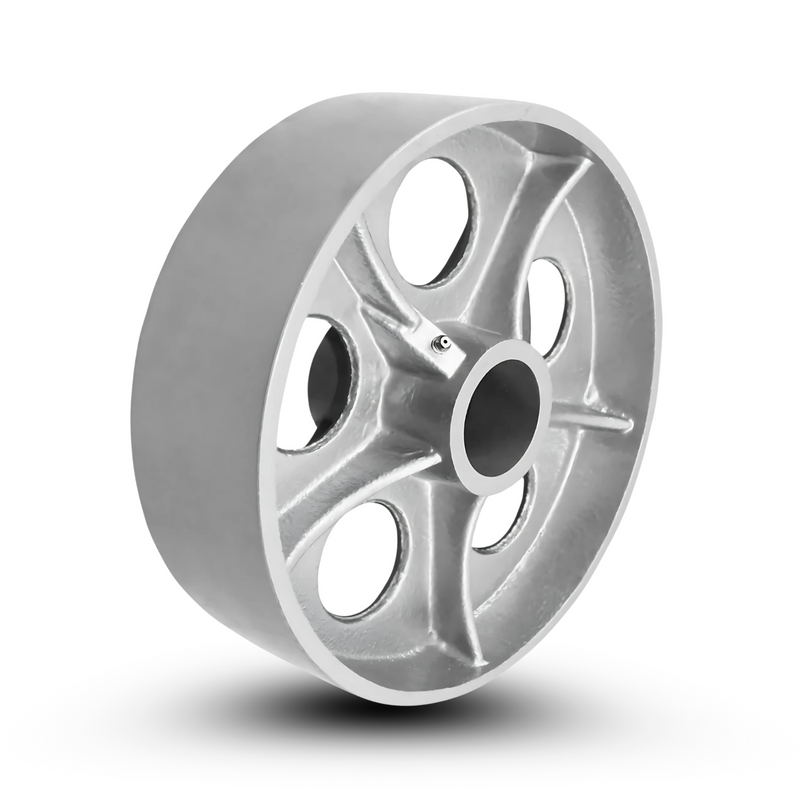
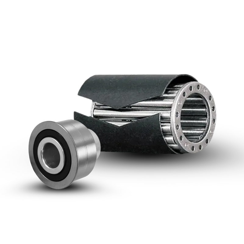
 Keyed Drive Wheels
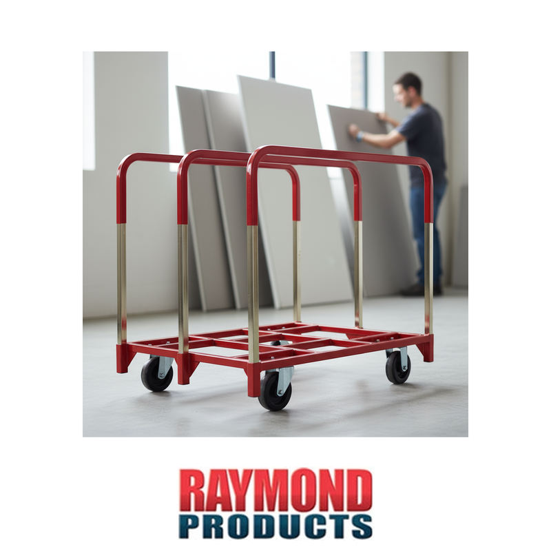
 Drywall Cart Casters
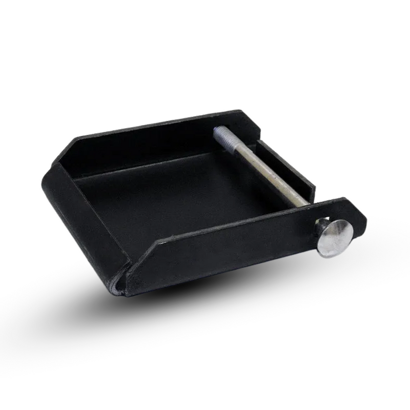
 Skid Wheels & Casters for RVs
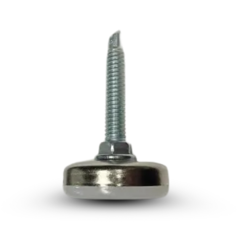
 Leveling Casters
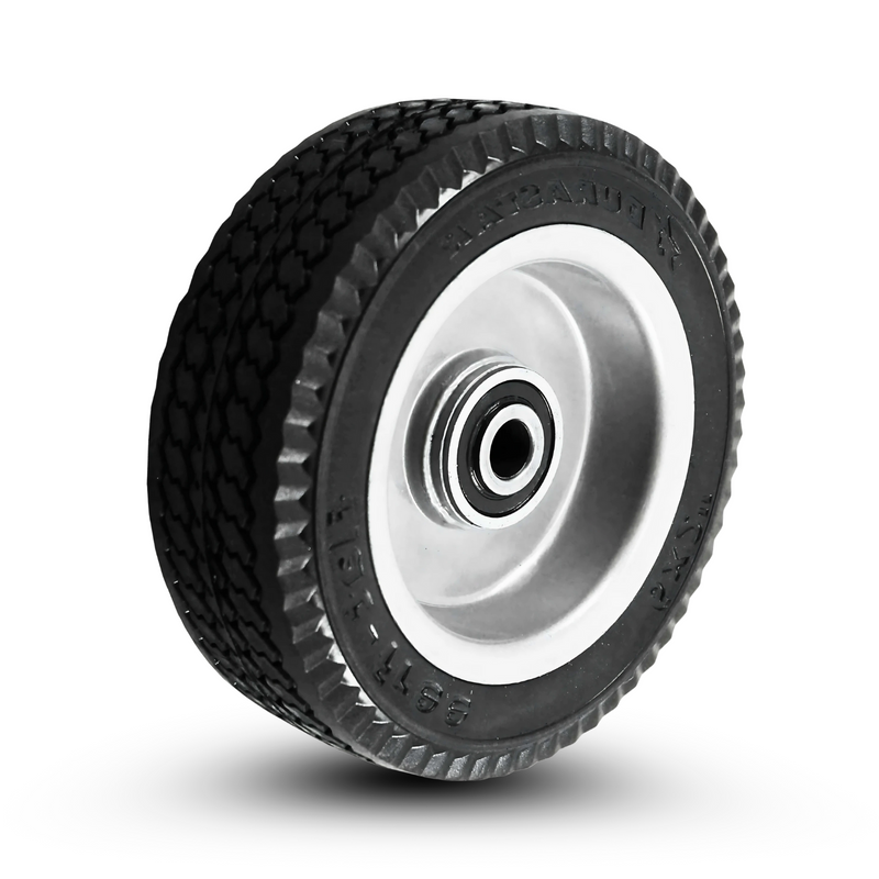
 Shopping Cart Wheels & Casters
 Band Equipment Casters & Wheels
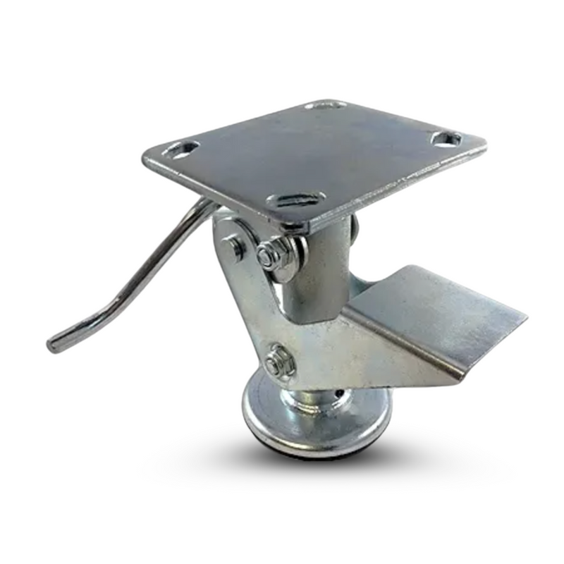
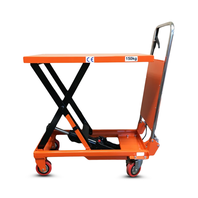
 Low Profile Casters
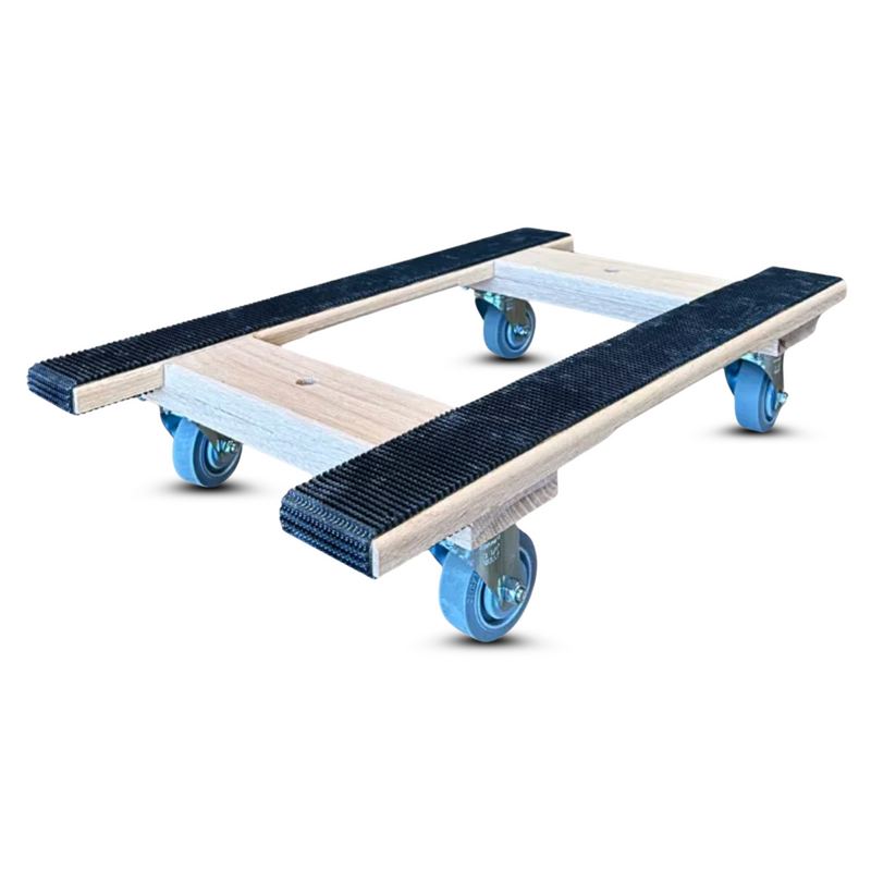
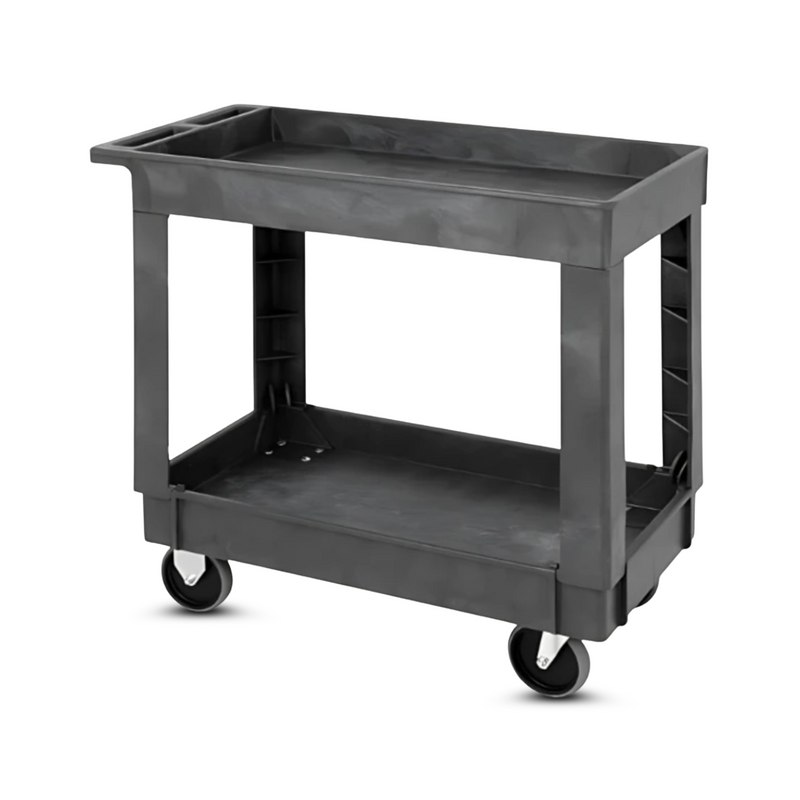
 Cart Wheels & Casters
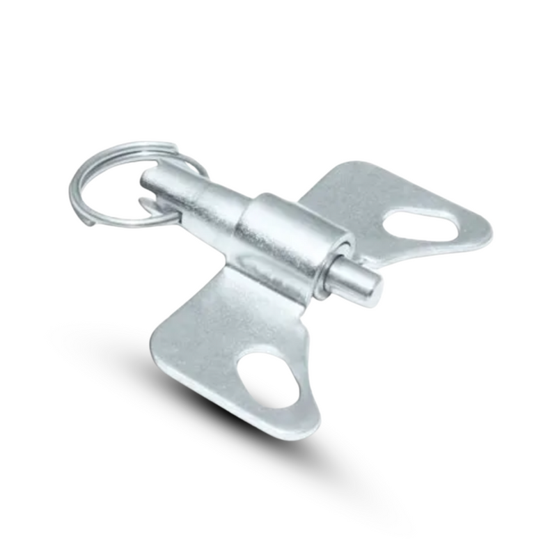
 Toolbox Caster Sets
 Bakery & High Temperature Casters
 Kitchen Prep Table Caster Sets
 Wire Shelving Casters
 Silent Glide Casters


A tall, narrow cart with a high load tips long before it feels unstable. This tool estimates the tilt angle at which your cart tips, a relative tip-over risk rating, and the turn speed that would roll it, from the load weight, its center-of-gravity height, and the caster wheelbase.
A cart tips when its center of gravity passes outside the wheelbase. The tilt angle that does it is the arctangent of half the wheel track divided by the center-of-gravity height, so wider casters and a lower load raise the angle and the stability. As a rule of thumb, keep the load's center of gravity below about two thirds of the wheel track, brake and turn slowly when it is higher, and widen the wheelbase or lower the load before adding speed.
Results update as you type. Wheelbase is the caster-to-caster spacing, not the deck size.
Sideways tip angle = arctan( (track ÷ 2) ÷ CoG height )
Critical lateral g = (track ÷ 2) ÷ CoG height
Critical turn speed = sqrt( critical g × 32.2 × radius )
This is a rigid static and quasi-static model: it assumes the load does not shift and ignores suspension and dynamic sloshing. The sideways angle is the limiting one because the track is usually narrower than the length. The critical turn speed is where centrifugal force in your tightest turn equals the tipping threshold; stay well below it.
Use this to compare designs and flag risk, not as a certified safety limit. For tall loads, powered tow, ramps, or public areas, have stability reviewed by an engineer.
A wider caster spread, a lower deck, dual-wheel casters, or directional and total locks all cut tip-over risk. Send us the cart and load and we will spec a stable footprint.
Request a Quote →A cart tips when its center of gravity moves outside the wheelbase, from a slope, a hard turn, an obstacle, or a high load. The taller and narrower the load relative to the caster spread, the smaller the tilt needed to tip it.
Lower the load, widen the caster spread, or both. Dual-wheel casters add roll stability, and directional or total locks keep it from spinning or creeping. Slowing down in turns and on ramps matters as much as the geometry.
It depends on the turn radius and the cart's tip threshold. The calculator estimates the critical turn speed where centrifugal force would tip it in your tightest turn; keep operating speed well below that, with margin for floor and load variation.
Reviewed by Bob Camp, Director of Caster Sales, 45+ years in the caster industry. Updated June 14, 2026.
Tip angle and critical speed are planning estimates from a rigid static model and are not a certified safety limit. Have tall, powered, or public-area carts reviewed by an engineer. CasterHQ, Mansfield, TX · 844-439-4335.


